Installing An Ar15 Lower Parts Kit Including The Buffer Assembly
(All you need to know, and maybe even a trick or two – pictures included!)
So, you did it! You milled out your first AR-15 80% lower that you got from 80lowers.com (shameless plug). Or, you bought a stripped lower, or just upgrading LPK’s (Lower Parts Kit) from a standard mil-spec LPK to something more ergonomically friendly. Hmmm… Come to think of it, there are a TON of different reasons you might be here. Either way, we are going to walk you through a very easy step-by-step process of installing your complete LPK and Buffer Assembly to get that lower functional. Let’s go!
We will start off with a “tooling list” that I would recommend to have on hand. Now, let me say this up-front: SOME of the tools are optional (you know, “right tool for the job” kind of thing), but not necessarily required to get the job “done”.
RECOMMENDED TOOLS FOR AR-15 LOWER PARTS KIT INSTALLATION
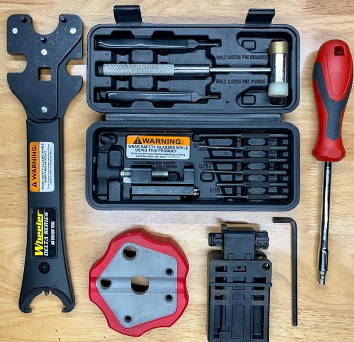
- Vice Block (or hammer block)
- Gun-Smithing Punch Set
- Gun-Smithing Hammer (nylon / brass combo)
- Cassel-Nut Wrench (Armors Wrench)
- Bit Driver / Bit Set (or Allen key for grip screw)
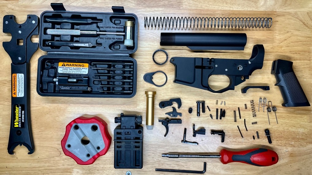
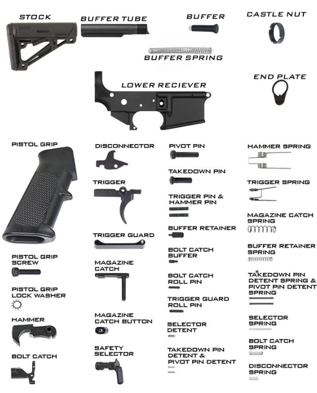
Now that you have all of your tools, and a clean work space – do a quick once-over of the LPK to ensure none of these little parts have gone missing (they do grow legs and walk away at times, especially the detents!). Understandably, you may not need every part – maybe you’re just jogging the ol’ memory on the Fire Control Group, but the parts list below is a complete list for the sake of completing the entire lower receiver assembly.
AR-15 LPK Installation Guide
There is a plethora of resources online and different articles for “how to install” anything on an AR-15, so just know up-front; some of the steps that I follow may deviate from, or be completely different than what other sources show – I like to use the “front-to-back” method (start at the front of the receiver and work my way backwards) when I assemble lowers. And, you may find your own unique way of completing the steps as well.
Either way; no need to fret! As the old saying going “there are many ways to skin an AR-15”… I mean, a “cat”, or whatever… So, we will perform a quick function check at the end of each step in the process. FYI – I recommend doing this regardless of what source you get your “how to” info from to ensure that your AR-15 lower functions as intended.
Step 1: Installing the Pivot Pin
Parts Required: Pivot Pin, Pivot Pin Detent, Detent Spring (use parts guide above as needed).
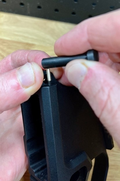
*Remember those couple of tricks I said you might learn here; this is one of them. Now, it is going to be easier done than said (only because it sounds odd typing it out). I’ve mumbled many 4 lettered words while crawling on the floor looking for a detent or spring when I first tried the typical “small flat-head screwdriver” approach, so just trust me on this one. It is much easier and you have more control of the tiny little parts when you do it this way.
Personally, I do not use the vice-block in this step. I start by holding the receiver in my left hand (I am right handed) and insert the Pivot Pin Spring into the hole. Then I place the Pivot Pin Detent on top of the spring and balance it using two fingers from my left hand as a guide. Next, take the end of the Pivot Pin and start to press down and in on the detent and spring until the Pivot Pin drops into place. BAM! You’re welcome!!
Slide the Pivot Pin in and out to check for proper function.
Step 2: Installing Magazine Catch
Parts Required: Mag Catch, Mag Catch Button, Mag Catch Spring
So, I did say “there are many ways to skin an AR-15”, but this next step does need to be done BEFORE you install the Bolt Catch assembly (which we will do next). If you do this out of order, the Bolt Catch will interfere with the installation of the Mag Catch assembly, and you’ll end up taking that back apart.
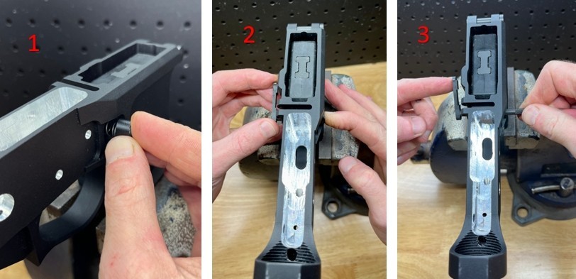
First, insert the Mag Catch Spring on the right side of the lower receiver. Next, place the Mag Catch Button on top of the spring and press inwards applying pressure and compressing the spring until the Mag Catch Button is in the hole. Note: The Mag Catch Button does not have to be fully seated in the hole, it just needs to be inserted enough that the button cannot move out of place with the spring tension that is being applied.
Then, insert the Mag Catch into the left side of the lower receiver until you feel it touching the Mag Catch Button. Start turning the Mag Catch clock-wise (righty-tighty / lefty-loosey) until it engages the Mag Catch Button threads by a couple of turns Note: It does not have to be a particular amount of turns, you just want thread started so you can remove your hand from the Mag Catch Button and the assembly will stay in place.
Now, using the back of a punch, press the Mag Button in until it stops. This will push the Mag Catch away from the receiver on the opposite side so that you can continue threading the Mag Catch until it is flush with the top of the Mag Button.
Insert a magazine and then release it to check for proper function.
Step 3: Installing the Bolt Catch
Parts Required: Bolt Catch, Bolt Catch Spring, Bolt Catch Roll Pin, Bolt Catch Buffer (aka Plunger)
First insert the Bolt Catch Spring and then the Bolt Catch Plunger (smaller end of the plunger fits inside of the spring) on the left side of the lower receiver. Then place the Bolt Catch into place and insert a temporary “retainer pin”, sometimes referred to as a “slave pin” to keep the assembly in place (I use a small punch, but any type of pin that fits will do). Now, using your gunsmithing hammer and punch, gently drive the roll pin into place. Note: The “slave pin” will start to back out as you drive the roll pin into place. You may need to apply slight pressure with your finger onto the Bolt Catch as the slave pin is backing out and the roll pin is moving into place.
*If your lower comes with a “threaded” Bolt Catch hole, you will not have a roll pin and will disregard that portion of the instructions. You will need a threaded Bolt Catch Pin in place of the roll pin (which may or may not be included in your LPK). Insert the threaded pin into place, securing the Bolt Catch, and then thread until it stops. I typically use a Loctite on this pin to ensure it will not back out while you’re sending rounds down range – you don’t wanna be “that guy” who was looking for parts that fell off of his build at the range…
Press the bottom of the Bolt Catch for proper function.
Step 4: Installing the Fire Control Group (trigger group)
Parts Required: Trigger, Trigger Spring, Hammer, Hammer Spring, Disconnector, Disconnector Spring, Trigger & Hammer Pins
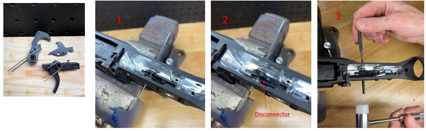
I like to start by installing all 3 of the springs onto their respective parts. Orient the Trigger and Hammer Springs as shown in the picture. Install the Disconnector Spring onto the trigger bar with the “bell shaped” end of the spring facing down (notice one end of this spring is flared).
Now, drop the Trigger into place inside of the trigger pocket, visually aligning the holes, and slide a “slave pin” (again, I use a punch for this) into the trigger pin hole to temporarily secure the trigger. Next, slide the slave pin out just far enough to drop the Disconnector into place. Pressing down on the Disconnector to align the holes, slide the slave pin back into place to hold the entire assembly together.
You are now ready to install the Trigger Pin into the assembly.
Slide the slave pin back just far enough to insert the Trigger Pin into the side of the receiver and start tapping into place. Note: The “slave pin” (or punch) is only meant to hold the assembly in place, not to perfectly align the parts. With that said, you will need to “wiggle” the trigger assembly by pressing down on the disconnector to align the holes while tapping on the Trigger Pin with your hammer.
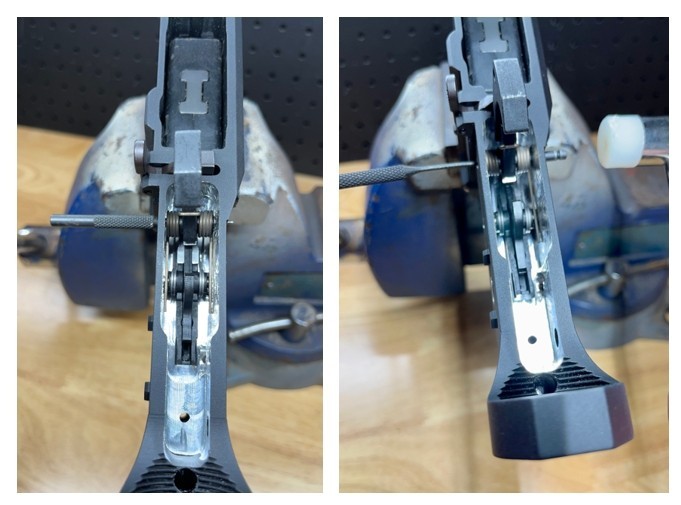
For the Hammer assembly (pictured above), ensure the spring is oriented correctly and then place the Hammer Spring legs on top of the Trigger Pin. Pressing firmly against the spring tension, align the hammer and receiver holes and insert a slave pin to hold the assembly into place.
Now, follow the same process as the Trigger Pin installation; slide slave pin back, insert Hammer Pin, wiggle / tap into place.
Note: You can perform a “partial” function check of trigger operation at this point. “Partial” as we have not installed the Safety Selector yet.
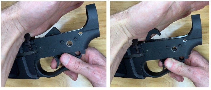
Trigger Group Function Check:
With the hammer in the rear (cocked) position, place the palm of your hand over the hammer (as shown in the picture above). Note: The purpose here is we want to prevent the hammer from making forceful contact against the front of the trigger pocket or the back of the Bolt Catch – this could potentially damage the parts.
Squeeze the trigger, and the hammer should fall as intended. Manually reset the hammer. This time, squeeze the trigger again, but do not let off of the trigger – maintain applied pressure as if you were still squeezing it. Manually reset the hammer, and then let go of the trigger. You should hear an audible “reset”, as the disconnector releases the hammer onto the sear.
You are ready for the next step.
Step 5: Installing the Safety Selector & Pistol Grip
Parts Required: Safety Selector, Selector Spring, Selector Detent, Grip, Grip Screw & Washer

Note: With the method I follow, in order to install the Safety Selector, the hammer must be manually placed into the rear (cocked) position.
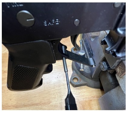
Slide the Safety Selector into place, aligning it into the selector hole on the opposite side of the receiver. Move the selector into the Safe or Fire position (either positions is acceptable). Next, flip the receiver upside down and drop the Selector Detent into the hole. Note: I like to take a small punch here and tap the detent to ensure it is fully seated and touching the selector. Most of the time, it needs a little help getting fully seated into position.

Now, insert the screw and washer into the bottom of the grip, and then insert the Selector Spring into the grip hole. Slide the grip onto the receiver, ensuring the spring aligns into the detent hole. Thread the screw into place until snug.
Check the Safety Selector for proper function. Remember to not allow the Hammer to make forceful contact with the receiver.
Step 6: Installing the Buffer Tube & Take-Down Pin
Parts Required: Buffer Tube, Castle Nut, End Plate, Buffer Retainer, Buffer Retainer Spring, Take-Down Pin, Take-Down Pin Detent, Take-Down Pin Detent Spring
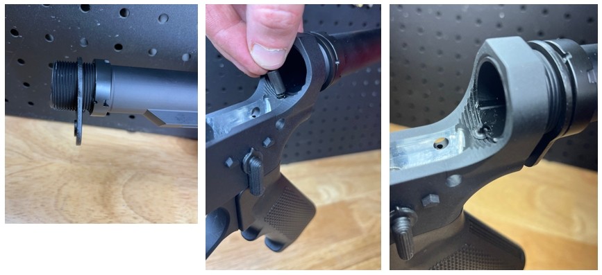
Start here by threading the Castle Nut onto the Buffer Tube with the notches facing to the rear. Slide the End Plate onto the Buffer Tube with the protrusion facing the receiver. Thread the Buffer Tube onto the receiver until it is flush with the retainer hole. Do not thread it past “flush”, as this will prevent the Buffer Retainer from being installed.
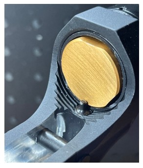
Then, drop the Buffer Retainer Spring into the hole on the receiver, and place the Buffer Retainer on top of it. Pressing down firmly (and covering your eyes… lol), thread the Buffer Tube over the top of the retainer hole, which will secure the Buffer Retainer into place. Note: The amount of required turns of the Buffer Tube will differ between buffer tube / lower receiver combinations. The key is to thread the Buffer Tube far enough in that it engages the Buffer Retainer “base” and not the “post” (as pictured).
Once you have completed that, it is time for another one of those tricks I told you about! Again, easier done than written, but pictures below will help:
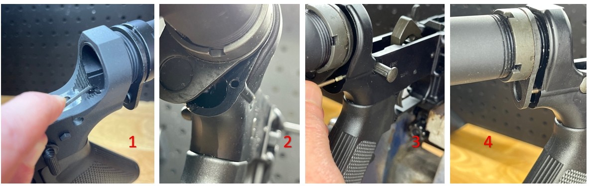
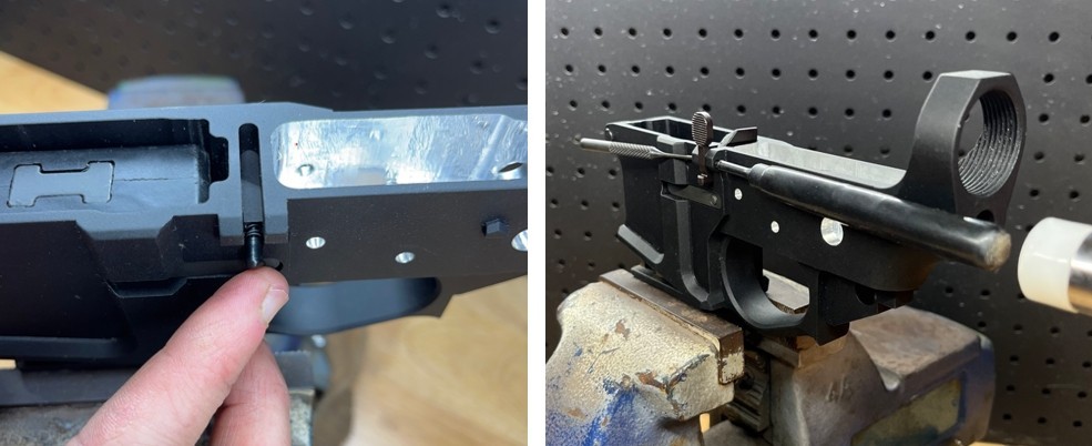
With a small punch, press down on the Buffer Retainer and turn the Buffer Tube slightly to the right (clock-wise), just enough to cover up the Buffer Retainer. The point here is to open up the rear hole that houses the Take-Down Pin Spring and Detent – which we will be installing next. And trust me, much easier than doing one of those “small flathead screw driver” fumbles…
Next, insert the Take-Down Pin into place and ensure the slot in the pin is facing towards the rear hole where the detent will properly engage the pin. Now, insert the Take-Down Pin Detent into the rear hole, followed by the Take-Down Pin Detent Spring.
Then, slightly rotate the Buffer Tube to the left (counter clock-wise) until the Buffer Tube is properly aligned. You will need to shift the Take-Down Pin Detent Spring underneath the End Plate, and then press the spring into place using the End Plate. Thread the Castle Nut snuggly up against the End Plate. Tighten with Armors Wrench.
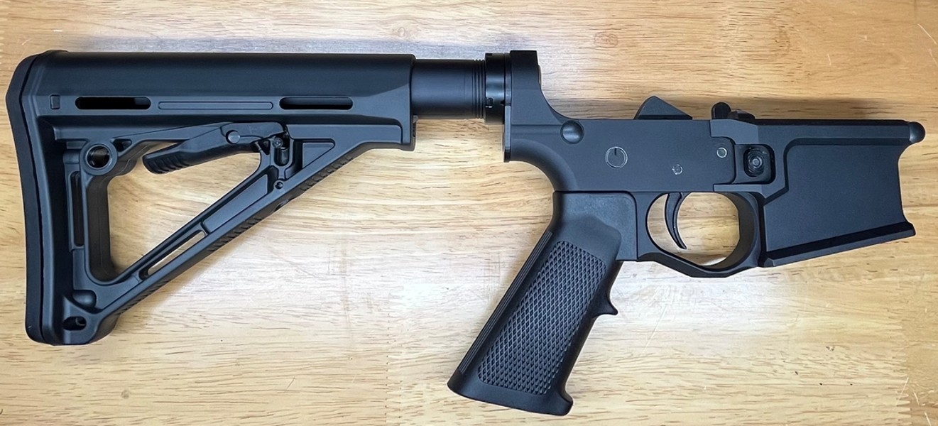
Install the Buffer Spring into the tube, and then the Buffer. Press firmly against the spring tension until the Buffer is held into place by the Buffer Retainer. Lastly, install the Stock of your choice onto the Buffer Tube.
Slide the Take-Down Pin in and out to check for proper function.
Step 7: Installing the Trigger Guard
Parts Required: Trigger Guard, Trigger Guard Roll Pin
Your lower may come with an integral trigger guard (like the one I used for most of this article), so disregard this step if so. And, for those of you who do need to install a trigger guard: Not all Trigger Guards are created equal, but this is a relatively simple task regardless of the “exact” style you may have.
Align the rear trigger guard holes and insert the Trigger Guard Roll Pin. With your gunsmithing hammer and punch, slowly tap the roll pin into place. The front trigger guard hole may be threaded, or may have a detent “button” that can be pressed and moved into place. I am trusting you got this by now – you know what to do!
DONE!!
Well, you just completed your lower receiver! Now slap that upper on and go burn some powder!