HOW TO COMPLETE AR-15 UPPER ASSEMBLY
The ocean of options on an AR-15 Upper Receiver is vast. There are almost as many options as there are in the beer aisle of that dumb new “fancy” grocery store down the road they just built… my wife likes to go there even though they are 10x’s more expensive – which, at the end of the day is setting me back on my next build – (Me: “This grocery store is cutting into my build money!”). But, I digress…
Anyhow – I am confident that if you have the basics down for assembling a Mil-Spec AR-15 upper, then the variations between manufacturers will be much less difficult to figure out. So – Let’s go!
As always, we will start off with a “tooling list” that I would recommend to have on hand. Now, let me say this up-front: SOME of the tools are optional (you know, “right tool for the job” kind of thing), but not necessarily required to get the job “done”.
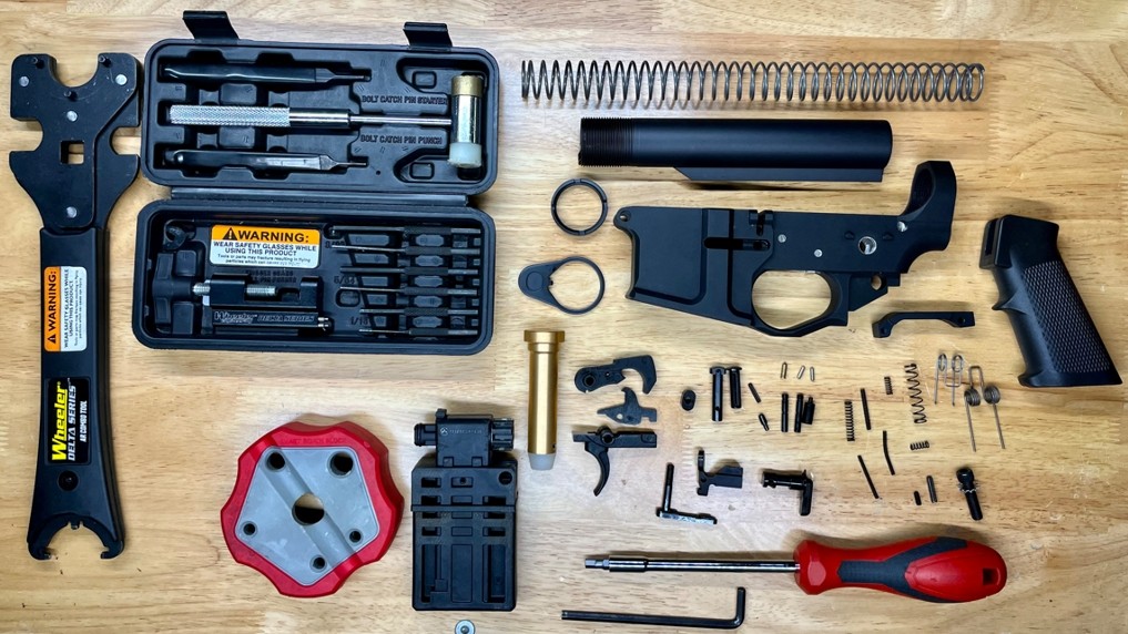
RECOMMENDED TOOLS FOR COMPLETING AR-15 UPPER ASSEMBLY
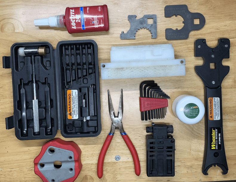
- Vice & AR-15 Vice Block (or a “reaction rod”)
- Hammer Block
- Moly-Lube (or some type of “anti-seize” / thread grease)
- Gun-Smithing Hammer & Punch Set (nylon / brass combo hammer)
- Barrel-Nut Wrench / Torque Wrench (Armors Wrench – needs ½” drive slot for torque wrench, as the Barrel Nut requires torqueing – different types shown in picture above)
- Bit Driver / Bit Set (or Allen key set)
- Needle-Nose Pliers
- LocTite
Now that you have all of your tools and a clean work space, let’s do a quick once-over of the required parts to ensure nothing has gone missing! Understandably, you may not need every part listed – maybe your Upper Receiver does not have a Forward Assist or Dust Cover, or maybe you have a Side-Charging Upper, but the parts list below is a complete list for the sake of completing the entire Mil-Spec Upper Receiver assembly with a free-float hand-guard.
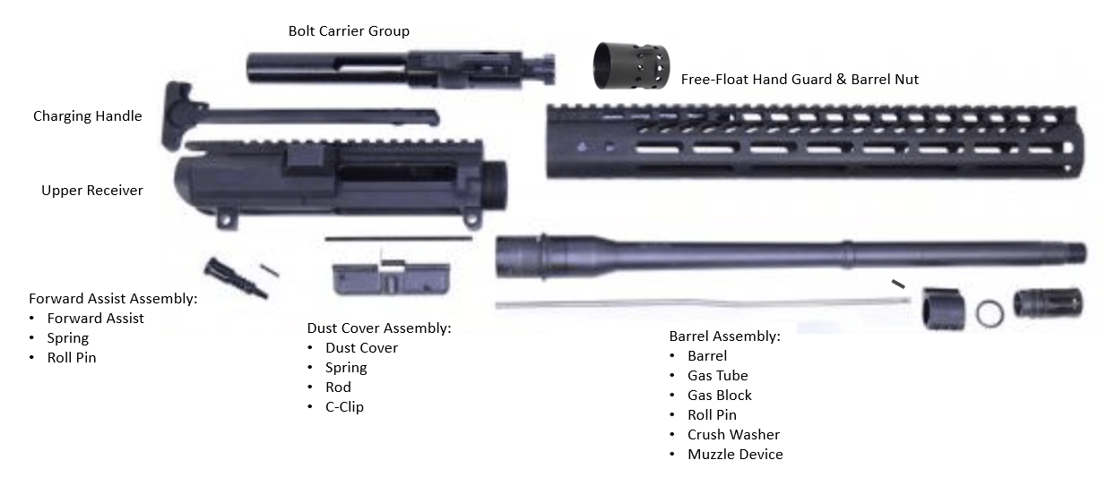
AR-15 COMPLETE UPPER ASSEMBLY
Installation Guide
*Note: There is a plethora of resources online and different articles for “how to install” anything on an AR-15, so just know up-front; some of the steps that I follow may deviate from, or be completely different than what other sources show. You may find your own unique way of completing the steps as well. Either way; no need to fret! As the old saying goes “there are many ways to skin an AR-15”… I mean, a “cat”, or whatever… So, we will perform a quick function check at the end of each step in the process.
FYI – I recommend doing this regardless of what source you get your “how to” info from to ensure that your AR-15 lower functions as intended.
Step 1: Installing the Forward Assist
Parts Required: Forward Assist, Spring, Roll Pin (use parts guide above as needed)
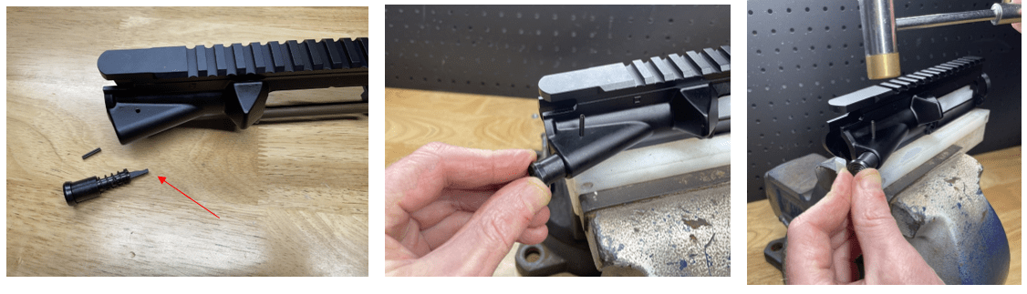
This is a fairly simple step. I typically start by getting the Roll Pin started first, so that I am not playing the “Hey, wife – I need 3 hands” game once I am trying to get the Forward Assist in place. Don’t worry, you’ll see what I mean shortly.
Next, place the spring onto the Forward Assist, and orient the Forward Assist Pawl (the little “tooth” thingy) facing towards the inside of the receiver (as shown in the picture above). Then, place the Forward Assist into the Upper Receiver, slightly pressing against the spring tension. Note: It does not take much effort to press the Forward Assist in far enough that the Roll Pin will do its job of keeping the Forward Assist in place – too much pressure and the Roll Pin will get hung on the Forward Assist.
Lastly, tap the Roll Pin into place, without having to use 3 hands or deal with your wife! You’re welcome!
Press the Forward Assist Plunger in to check for proper function.
Step 2: Installing The Dust Cover
Parts Required: Dust Cover, Spring, Rod, C-Clip
This step can be a little tricky, as the Spring can give you fits when attempting to roll it into place. Be patient, it’ll be much easier as you do this a time or two.
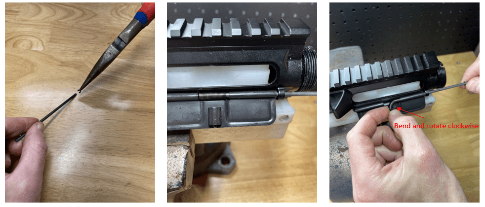
Let’s start with installing the C-Clip onto the Rod. Pretty self-explanatory step; a pair of needle-nose pliers comes in handy here (see image above).
Next, orient the Dust Cover onto the upper receiver (flat side faces outwards – detent tab faces the inside of the upper receiver when closed) and insert the Rod until it is slightly protruding thru the first hole in the Dust Cover (image above).
Then orient the Spring onto the Rod (longer spring leg towards the bottom, and on the right hand side – as shown above). You only want the spring started onto the Rod just far enough to hold it into place, as you will still need to rotate the opposite side of the spring 180 degrees. Note: I find that the more spring I can leave sticking out, the easier it is to rotate 180 degrees.
Finally, the tricky part! I like to start by bending the left hand side of the spring outwards to make this easier (which now you will see why I leave as much spring off of the Rod as possible). Now rotate the spring 180 degrees clockwise so that the small spring leg has tension against the upper receiver. While holding the Spring in place with your finger, slide the Rod thru the spring and the opposite side of the Dust Cover, securing the Dust Cover and Spring into place.
Close and open the Dust Cover to ensure proper function.
Step 3: Installing the Barrel
Parts Required: Barrel, Barrel Nut
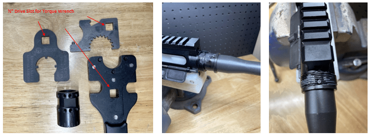
There are many many different types of Barrel Nut / Hand-Guard combinations out there. Some proprietary and requiring their own specialty tool to install, and some you can use a standard Armors Wrench to install – all of the options need the ½” drive slot for adapting the torque wrench to (as shown above). I actually use a couple different “Crow-Foot” adapters that fit most any Barrel Nut with flats on it and allow me to torque properly. If you have a different type than shown here, no worries. I think you will still be able to put the puzzle pieces together based on the fundamentals of the installation.
Start by applying a light coat of Moly-Lube onto the outside of the Barrel Extension, onto the Upper Receiver threads, and also a light coating on the inside of the Upper Receiver – this will make installation much easier, as well as future removal. Insert the Barrel into place, using the “index pin” for proper alignment, and then thread the Barrel Nut onto the Upper Receiver until it is holding the Barrel “snug” in place.
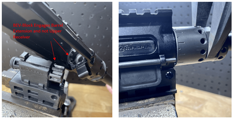
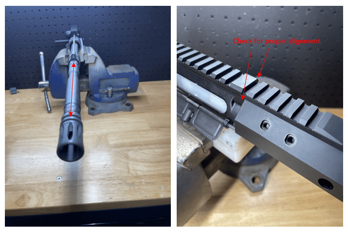
There are also a few different types of tools that can be used to torque the Barrel Nut onto the Upper Receiver. I personally do not use the Upper Receiver Action Block for this, as is puts most of the pressure onto the Upper Receiver when torqueing. I like to use the BEV-Block (Barrel Extension Vice – shown above) or a Reaction-Rod that does not apply pressure to the Upper Receiver at all.
Now, using your Armors Wrench (or specialty wrench), torque the Barrel Nut to the specified torque value. *Note: Torque values are normally given by the manufacturer of the Hand-Guard, and in general will be between 35-80 ft-lbs. One reason the range is so wide is because in some cases the Barrel Nut has to be “timed” for proper alignment with various Hand-Guard styles. Therefore, a standard torque value is not possible to achieve in all circumstances. They will also typically give some guidance on torqueing, loosening and re-torqueing between 1-3 times. I generally follow the 3 times process (torque, loosen, torque, loosen, final torque). Follow the Manufacturers recommendations to the best of your ability.
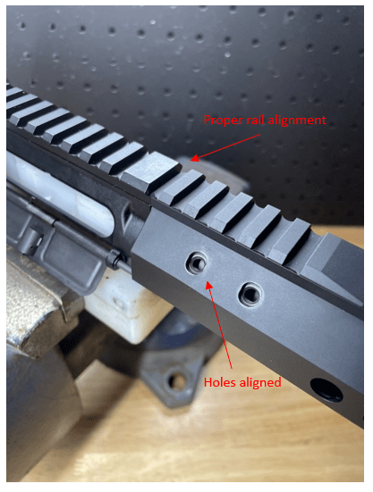
As long as you have properly torqued the Barrel and checked Hand-Guard alignment (shown above), there is no other check for proper function yet. *Do not tighten Hand-Guard – only check alignment.*
Step 4: Installing the Gas System
Parts Required: Gas Block, Gas Tube, Roll Pin
Gas system parts come in various sizes and lengths depending on Barrel Diameter and Gas Port to Barrel Extension (end of the barrel extension) measurements. We will do a deep dive later on, so for now all you need to ensure is that the Gas Block and Gas Tube you purchase(d) fit the Barrel properly. We will be using a .750 gas block and a Carbine Length Gas Tube on this Mil-Spec build.
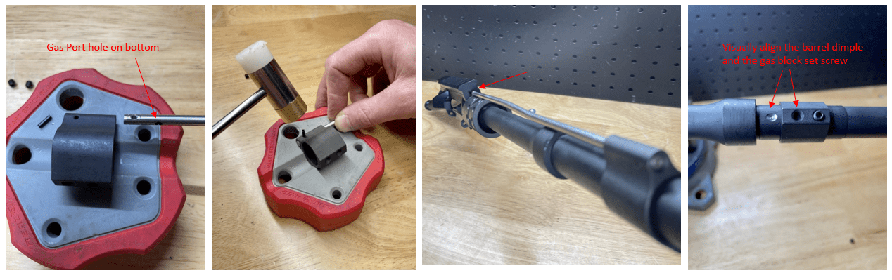
I like to start here with getting the Roll Pin started onto the Gas Block. It can also be a bit of a pain to start this tiny Roll Pin – needle-nose pliers come in handy here too! Orient the Gas Tube with the gas port facing down (as shown above) and insert the Gas Tube into the Gas Block. Visually align the holes and drive the Roll Pin into place.
Next, slip the Gas Block onto the Barrel and guide the Gas Tube into place on the Upper Receiver (as shown above). Now flip the Barrel over and visually align the dimple with the first set screw hole on the Gas Block (picture shown above).
Once you have the dimple and set screw hole aligned, thread the set screw into place until the set screw barely touches the Barrel. You should be able to “wiggle” the Gas Block slightly and ensure that the set screw has fallen squarely into the center of the dimple – this helps ensure proper alignment of the Gas Port on the Barrel to the Gas Block.
With the first set screw snug, remove the second set screw (closest to the end of the Barrel) and apply a small amount of LocTite and then tighten firmly. Now repeat on the first set screw. Note: Some Manufacturers recommend tightening the Gas Block to 30-35 in/lbs (NOT ft/lbs). Follow the manufacturers recommendations to the best of your ability.
No function check required at this step.
Step 5: Installing the Muzzle Device and Hand-Guard
Parts Required: Muzzle Device, Crush Washer, Hand-Guard, Hand-Guard Mounting Hardware
Start by orienting the Crush Washer onto the Barrel with the tapered side in and “fat side” (or cup side) facing out towards the Muzzle Device.
Next, thread the muzzle device on and tighten with your Armors Wrench to properly align it. With this A2 Birdcage, the top notch should align perfectly with the center of the Gas Block (as shown above).
Now for the Hand-Guard. I’ve already mentioned the plethora of options here. Some Hand-Guards may have anti-rotation tabs, some may have a “split rail” style mount, and so on… Again, the concept is similar to mount a Hang-Guard onto a Mil-Spec Upper Receiver. And by this point you are practically a pro, right…?
The important thing here is alignment – especially if you are using Iron Sights of some sort. The Front Sight will be mounted to the Hand-Guard, and the Rear Sight mounted to the Upper Receiver. In that case, obviously you want the alignment to be flawless.
Similar to the Gas Block installation, I like to get the alignment just perfect and then remove one screw at a time and apply some LocTite before final tightening. Also, similar to the Gas Block, some Manufacturers have a recommended torque value for tightening the Hand-Guard screws. It is usually around 35 in/lbs, but follow the Manufacturers recommendations to the best of your ability.
No function check required at this step.
Step 6: Installing the Charging Handle and Bolt Carrier Group (BCG)
Parts Required: Charging Handle, Bolt Carrier Group (BCG)
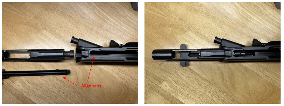
Start with the Upper Assembly flipped up-side down and the Charging Handle up-side down (this gravity thing will help keep everything together for this step), align the “tabs” on the Charging Handle with the cut-outs inside of the Upper Receiver – you’ll see what I mean when you look inside the receiver. The Charging Handle should fall into place and slide rather freely back and forth.
Now, pull the Charging Handle about ¾ of the way out, but do not let it come out of the guide rails. Flip the BCG up-down and insert it, along with the Charging Handle, simultaneously into the Upper Receiver. It should “lock” into place.
Move the Charging Handle and BCG assembly back and forth to check for proper function.
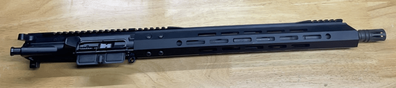
DONE!!
Well, you just completed your upper receiver! Now slap that lower receiver on and go burn some powder!